
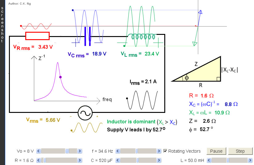
RLC a.c. Series
L is a pure inductor (i.e., no internal resistance); C is a pure capacitor and R is a pure resistor.
|
Internal Links : |
- The small square at the left of each waveform vibrates at the instantaneous value of the voltage or current it represents.
- The subscripts "o" and "rms" stand respectively for peak value and root-mean-square value.
- The supply voltage (A) and the circuit current (E) will always have a phase difference φ. The phase difference can be found by using the triangle (H). If the inductive reactance (XL) is greater than the capacitive reactance (XC), the supply voltage will lead the current; if the inductive reactance is smaller than the capacitive reactance, the supply voltage will lag behind the current.
- The p.d. across the resistor (B) oscillates inphase with the current (E).
- The p.d. across the capacitor (C) lags behind the current (E) by π/2.
- The p.d. across the inductor (D) leads the current(E) by π/2.
- In other words, (C) and (D) are always in antiphase.
- The four RMS volatges are related by the triangle (H).
- The curve (F) shows the variation of the reciprocal of the impedance against frequency.
- (G) shows three rotating vectors (phasors), their projections on the y-axis corresponds to the three instantaneous voltages.
- Series resonance is achieved by adjusting f, L or C such that the purple dot is exactly at the highest point of the curve (F).
- At resonance, (i) phase diff = 0 and (ii) Z = R. Therefore, (A) and (B) become exactly identical, (A) and (E) are inphase. The circuit current (E) is the largest.
- At resonance, the p.d. across the capacitor (C) and that across the inductor (D) may be large in magnitude but their sum is zero.